Blog
-
Termi2 – a Typewriter That Answers Your Questions
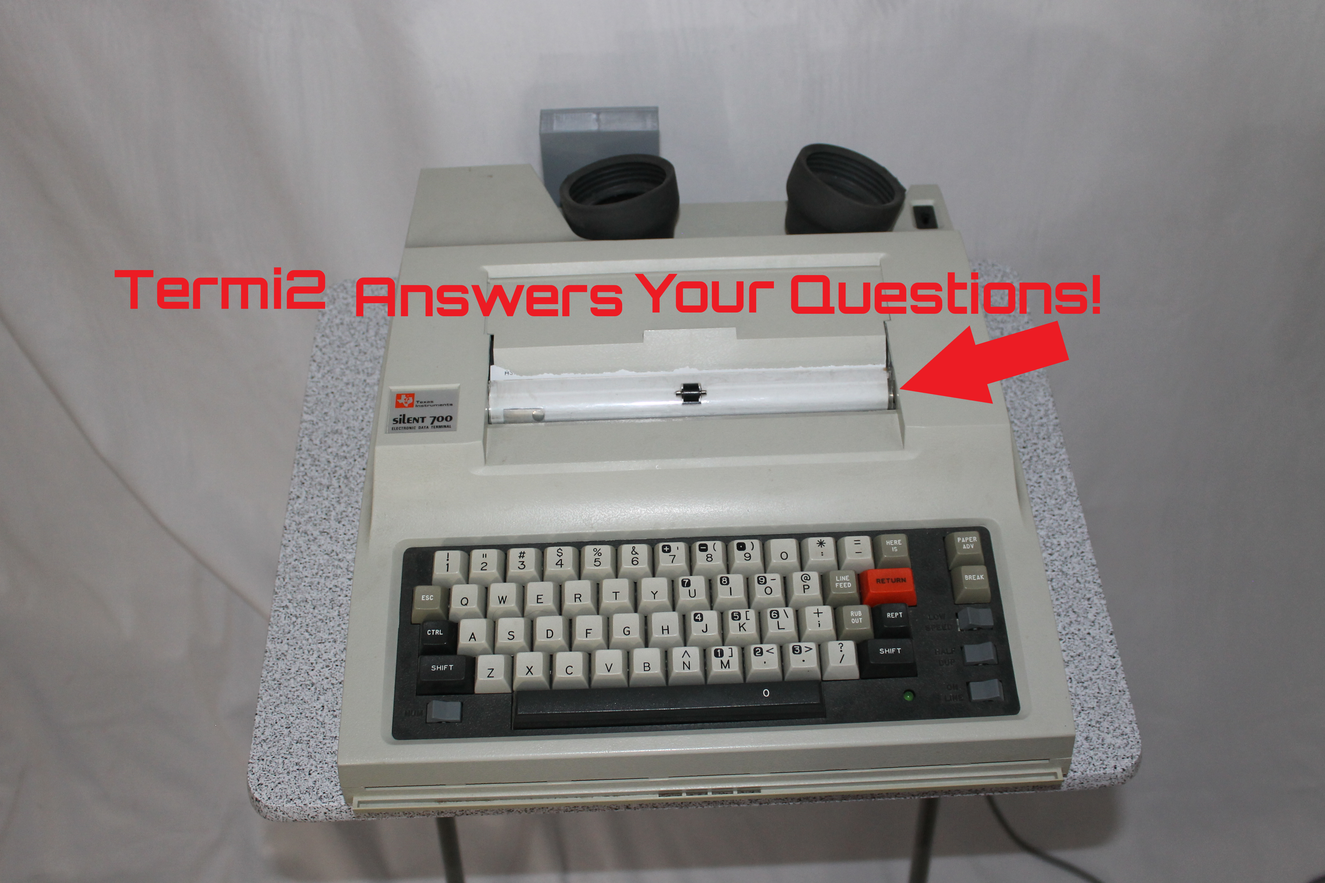
Termi2 is a vintage TI Silent 700 (Model 745) with an added device of my own design that lets users type questions and receive printed answers from Wolfram Alpha.
-
Comparatron – DIY Digital Optical Comparator
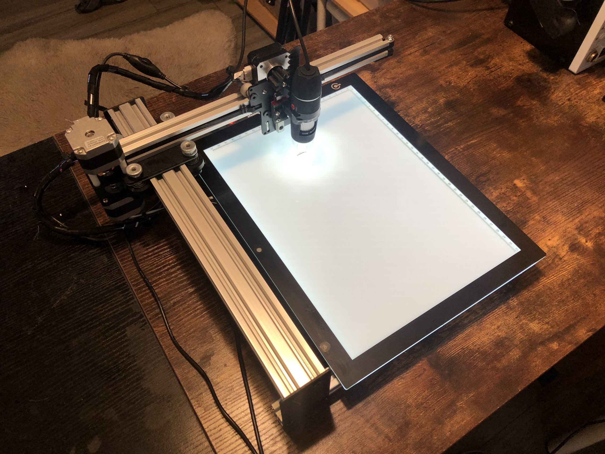
Comparatron is my own digital optical comparator design. It is open source and anyone can build it and use the software interface I programmed.